This page is here to illustrate some of the issues one may encounter during a Bridgeport variable speed head rebuild. As with everything mechanical some components will wear and eventually will need attention to get back into service. Let's have a look at the Vari-Disc mechanism.
Vari-Disc Drive
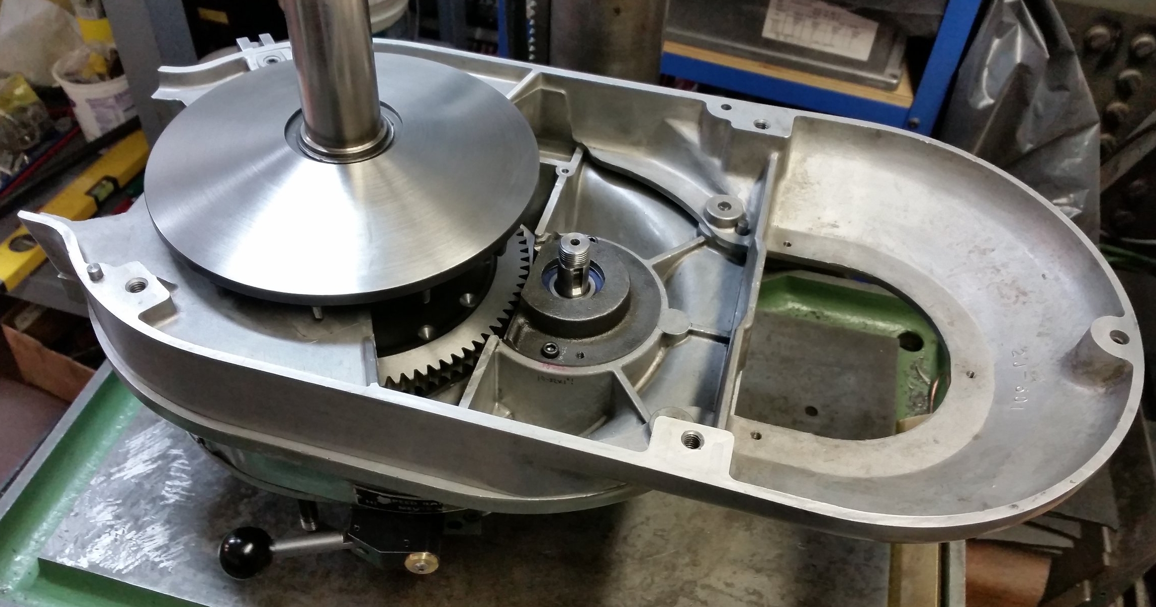
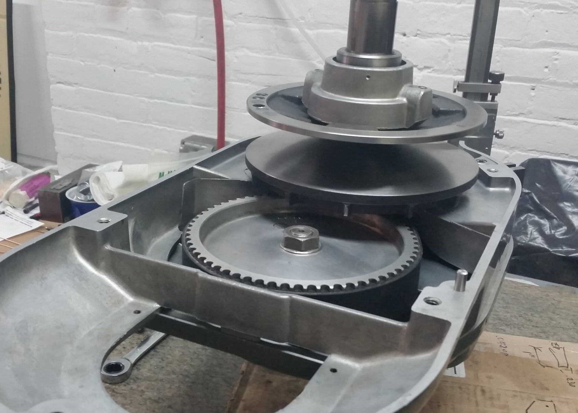
Here is an image of the front vari disc assembly. The top cone slides on the drive drive shaft (spindle pulley hub) and the lower cone is fixed to the shaft and rotates on a bearing in the housing. The drive belt not shown, connects from there to the motor.
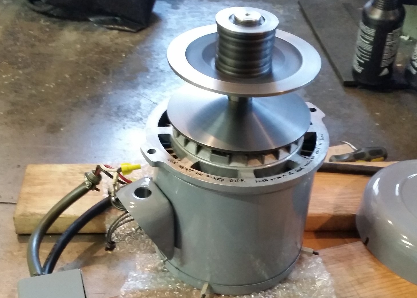
This is the vari disc assembly on the motor. The top cone slides on the motor shaft and the bottom is fixed. In this picture, the assembly is spinning with the spring compressed in the upper most position to check for balance.

The two moving cones contain low friction bushings and keys. As shown here the black bushings line the bore. These bushings are consumable items and are a cause for vibration when worn out. If the head exhibits a rattling sounding other than bearing noise, it's most likely worn bushings.

Hardinge and others sell these replacement bushings. The kit H+W sells was purchased. It included the bushings, urethane adhesive, drive keys and alignment pins. The steel pins were a good fit and worked well in creating the correct clearance for sliding on the motor shaft and spindle pulley hub. However, they are too short to chuck up in a lathe to aid in bonding.

During bonding, the pin was located as concentric as possible on a lathe and runout checked on the disc. All looked good before the adhesive set. After however, you can see how far out things got! One possibility was the expansion of the urethane adhesive throwing things off or the disc was not held in position long enough before the adhesive set. We opted to re-machine the cone surface mounted to the motor shaft.
Hardinge (Bridgeport) sells a vari-disc with the bushing already bonded/installed. It is pricey especially if you need two. In the long run this may be the cheaper option considering the time spent re-machining.
Another consideration is to make undersized bushings, bond them in then post machine the bore concentric. The problem with this option is the keyway slot in the bushing that will make for an interrupted cut when boring. Broaching the keyway after may break the bond. As is, nothing bonds well to low friction engineering plastics such as delrin.
If the pins were longer they could be chucked more accurately in a lathe during bonding to check runout. The ones purchased were designed to be assembled on the bench with the assumption that the bushing takes on the alignment of the bore.

To make things worse, the disc that slides on the drive hub was also out and besides re-facing also needed to have the ball bearing shaft re-machined. In order to fit the same bearing, material was removed from the od of the disc then replaced with a pressed steel ring which then was post machined to fit the id of the bearing. This was critical. Any runout here transmits vibration into the speed change plate and upper housing.
It is important to check runout with a dial indicator on the face of the discs as well as the bearing areas to get a sense of what my or may not be out of round. Never assume anything. Worth noting; it can be difficult to re-machine the vari-discs. They are made of cast iron and can be difficult to fixture rigidly enough to prevent chatter. Also the lathe needs enough travel on the cross slide. The machine used here is the Heavy 10" Southbend lathe. It is at it's limits for this job.
The stationary discs were also checked for wobble and we found uneven wear or warpage. The uneven highs and lows were corrected. For the most part, only light cuts were taken trying to get things within .002" or better. Now that we removed material, the previously balanced discs are now no longer in balance and need to be.

Static Balancing
This image shows a static balancing rig being used to get the front disc assembly with hub into static balance. Clay was used on the high spot then weighted and equal amount of iron removed on the heavy side by drilling.
The same process was repeated for the motor pulleys but done individually as the motor shaft assembly was too big to fit on the static balancer. This alone however did not guarantee a super smooth running machine. Dynamic balancing was the answer.
Today's sensor and software technologies make it possible for hobby grade balancers to offer low cost balancing solutions for the DIY individuals.
Professional options, often expensive, are found in well equipped electric motor repair and performance engine rebuild shops.

Dynamic Balancing
Shown here is balancing done on a single plane with the sensor simply taped to the motor housing. 4 point method was used successfully.
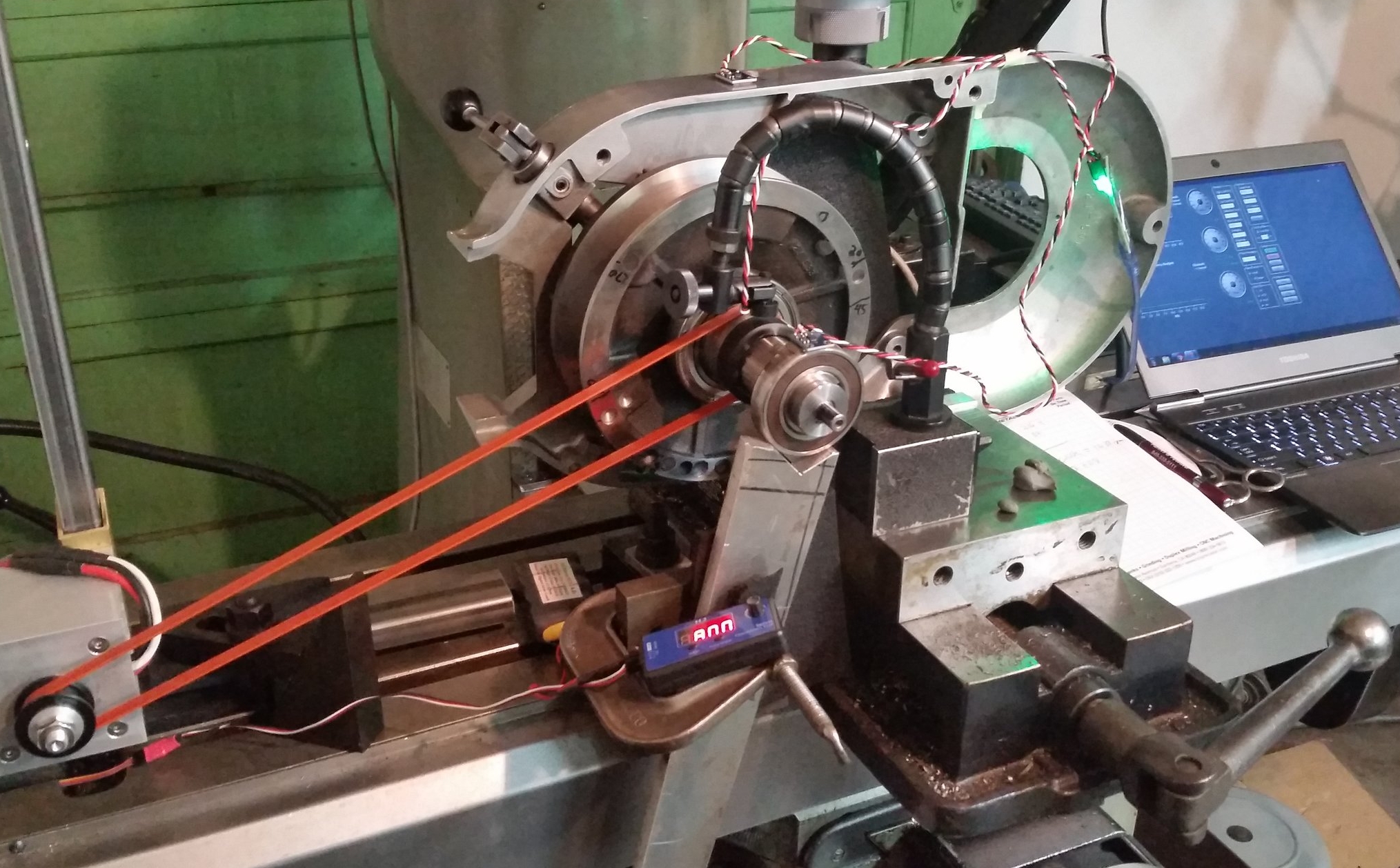
Balancing the front disc assembly using a hobby motor and speed control. This was not the most elegant setup but worked well enough to test up to 4000 rpm. The ideal setup would have a proper floating cradle arrangement to reduce harmonics.